Week 10 : 10/24/2022 - 10/31/2022
- Daniel Eisenbraun

- Nov 2, 2022
- 1 min read
After reviewing the feedback brought forward to us by Allen Jones from the IEEE and the group decided to use a higher capacity solar panel to both run the system and charge the car, I used my time to find a suitable charge controller for a lead acid battery, as well as re-work previous ideas related to the circuitry that had previously been proposed.
For the PWM Charge Controller, we will go with the Kimystam 20A Solar Charge Controller, for Lead-Acid Battery. (Note : This has since been changed to Devpko 30A Solar Charge Controller by Ian on 11/1/2022)

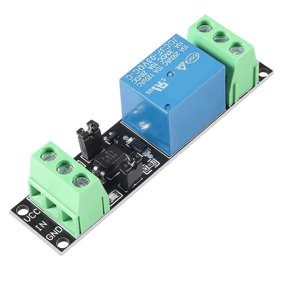
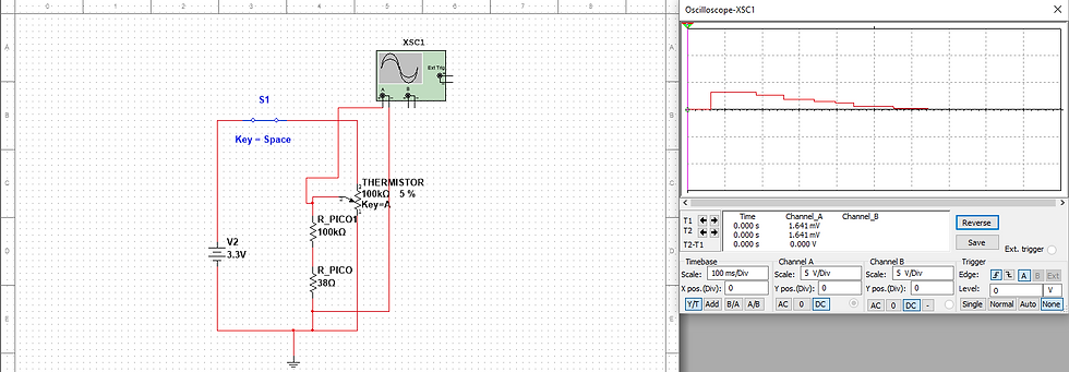
Given issues related to using P-MOSFETs in our control circuit design and testing revealing both an issue with the total output voltage being limited by the drain current of the MOSFET and the potential for electrical isolation issues out of the MCU, it was decided to use a set of relay boards. Some basic testing was done in Multi-sim with a circuit approximating the chip that will be used.


As well, Thermistor circuit previously proposed was deemed unnecessary. The resistance value of the Thermistor and GPIO are pin are such that the current driving the circuit will never pose a risk to the MCU. A simple voltage divider will be all that is needed to read the voltage of the MCU properly.

Lastly, the block diagrams were updated based on these changes and an MCU control diagram detailing the rough layout of connections to the MCU was made.


Comments