Weeks 16-21 : 12/5/2022 to 1/9/2023
- Daniel Eisenbraun

- Jan 15, 2023
- 2 min read
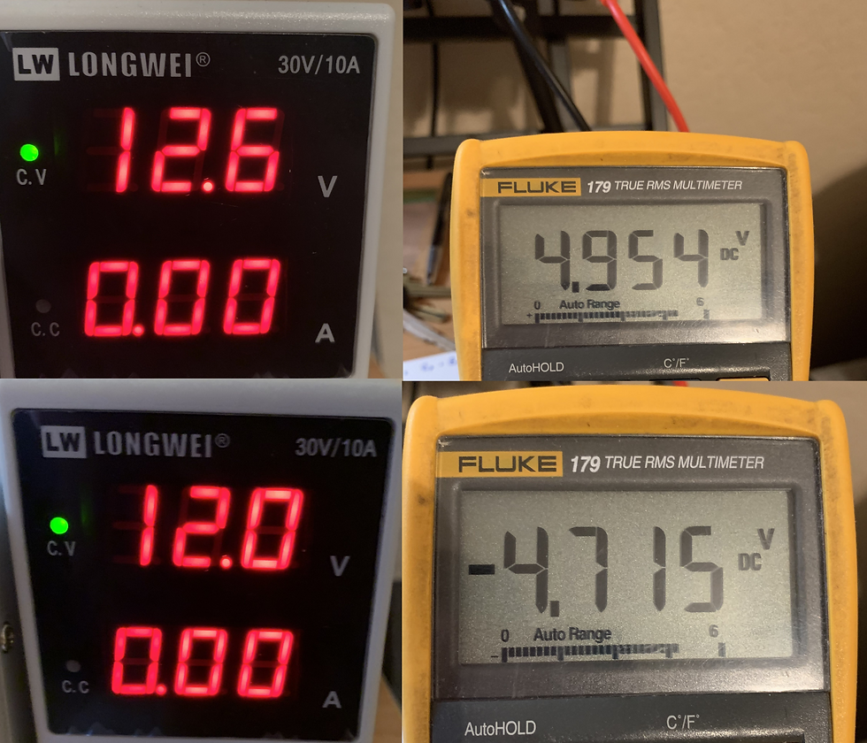
Over the break, a battery voltage monitoring circuit and Thermistor Circuit were designed and tested on the bread board. Initial testing was based on a maximum input voltage of 12.6V and relied on a simple voltage divider network to create a 5V signal corresponding to the 12.6V maximum with a 200mV difference between the maximum voltage used for our device and the minimum voltage for shutoff at 12V. Resistor network was built and tested on bread board as shown below.


During the break, Ian discovered that this configuration would not be sufficient to meet our needs as the technical maximum voltage of the battery could be as high as 15V and that a 5V signal was not what was needed by the Raspberry Pi Pico, rather a 3.3V input signal was required for the ADC to properly read it. The resistor network was reconfigured to meet these requirements as shown below.


From the maximum voltage of 15V down to 12V there is a 663mV difference and between the operational maximum of 12.6V down to 12V there is a difference of 131mV. The 663mV difference more than meets our requirements while allowing for a readable difference between 12.6V and 12V by the Raspberry Pi Pico ADC.
The Thermistor Circuit required a similar voltage division due to the maximum rating of the Pico, but this was much simpler as adding a single 100k resistor in series allowed for the voltage read by the ADC to be easily distinguishable based on the expected highs and lows. As the temperature increases, the resistance of the thermistor decreases and the opposite is true as the temperature decreases. At a minimum temperature of 0°C, assuming 3.3V applied to the circuit, the voltage will be 2.516V while at a maximum temperature of 60°C the voltage will be 650mV. This translates to approximately 17mV per 1°F of difference which is readable by the ADC which has a resolution of 8mV. An O-Scope picture of the increasing voltage with decreasing temperature and decreasing voltage with increasing temperature is shown below. (note : O-Scope out of calibration, actual result is -200mV)

Due to the risk of current into pins of the pico if voltage to the thermistor was applied directly from GPIO, a method of isolation was needed. The use of photocouplers was determined to be sufficient.
Supplies for the vehicle were gathered and checked to ensure physical functionality. The vent visors will fit as advertised and provide sufficient space for our fan assemblies with nuts/bolts/spacers. The terminal lugs and wiring to the PWM charge controller is correctly sized for proper connection to it's terminals. The Solar Panel required the additional purchase of IP67 connectors as the Panel did not come with any. As well, 2 pin connectors for the fans were ordered to ensure ease of connection when soldering/wiring is performed. 22AWG Wire was also purchases as the 18AWG Wire that was on hand may be too large for proper connections to the fans.

Comments