Week 21 : 1/9/2023 - 1/16/2023
- Daniel Eisenbraun

- Jan 17, 2023
- 2 min read
After discussion over the weekend of 1/7/2023, a need for a 3.3V source to power the relays was deemed necessary due the excessive current draw of 100mA to 150mA per relay. To this end, a set of on hand LD33V ICs was decided to be used as a means to power the relays. Each IC can take a 4V to 15V input from our PWM Charge controller and convert it into stable 3.3V output at up to 950mA. A total of 10 are on hand which should be sufficient to power all relays. An an IC hooked up to a relay with a simulated 3.3V trigger is shown below.

Fans were attached to the vent visors as planned, however, the overall size of the vent visors would not accommodate the original 44 fans that were planned, due to sizing constraints, only 10 were able to be placed on each front visor and 6 on each back visor bringing the total down to 32. This was deemed acceptable as the original experiments run which provided us with baseline data (and a reduction of internal temperature by 9°F) used a total of only 8 fans. While speculative, we believe 32 total fans will be sufficient to meet our goals.
Fans were checked for spacing against the window and no obstruction was found. No bends, cracks, or physical damage was incurred to the vent visors during the installation of the fans. It should be noted that this is not the *final* installation, we will need to seal the screws using a water proof sealant and secure the nuts to the bolts using loctite prior to finalizing the build, testing will need to be done prior to this however.

The Solar Panel was taken and placed on top of the the test vehicle and the voltage across open circuit voltage was tested to verify functionality.

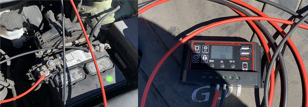
Once done, the PWM Charge Controller was wired to the car battery to also verify functionality and to test parameters of the charge controller. It should be noted, the lowest load disconnect voltage is 11.5V which means we will need to rely almost solely on the Raspberry Pi Pico to turn off fans and various electronics at our specified 12V minimum.

The solar panel was then attached to the charge controller which registered the input and began to charge the battery. The voltage of which hopped to 14.4V due to the input charge of the solar panel. Testing the output, I used a single 12V DC blower and found that there is an issue. The output of the PWM Charge Controller cannot be set, but is instead the current voltage of the battery meaning that an additional regulator will be needed at the output to ensure 12V DC is delivered to our fans rather than the 11.5V to 14.5V of the battery.

With this information, I discussed a possible solution with Ian and found a suitable regulator for our needs. The regulator in question can take an input voltage at 4.5V to 50V at up to 15A and can output a voltage of 10V to 60V at up to 12A (both output voltage and current controlled by potentiometers which are set by the user).


Comments