Week 21 : 1/9/23 – 1/16/23
- Ian Matheson

- Jan 18, 2023
- 4 min read
This week, Ian set out to test the newly revised thermistor circuit and revise the fan control block diagram, the MCU Pinout diagram, and the battery mode code. Ian also designed and tested an IR proximity sensor circuit and program.
Temperature Sensor Revision and Testing
During the group meeting on 1/8/23, Daniel had the idea to use photocouplers to isolate the outputs of each temperature sensor going into the ADC. The following circuit was designed and built on a breadboard using potentiometers.

Figure 1 – Photocoupled temperature sensor schematic

Figure 2 - Photocoupled temperature sensor on breadboard
To test whether the outputs were still dependent on each other, a measurement was taken with one potentiometer set midway while the other was set to its lower extremity. Next, a second measurement after changing only the second potentiometer to match the first.
Table 1 - New thermistor circuit test

The circuit succeeded in isolating the outputs of the two thermistor circuits. One concern with this circuit is that the voltage read by the ADC may be slightly inaccurate due to any voltage drop across the PC817’s phototransistor. When measured, however, only 0.0024 mV appeared across the pins. Regardless, the circuit can be calibrated to a known good temperature sensor by offsetting the input voltage in the code.
Revision of Fan Relay Groupings and Battery Mode Program
Due to the space limitations of the vent visors, the number of fans had to be reduced. The rear window visors could only fit six fans, while the front window visors fit 10. The group chose to reduce the number of relays from 32 to 24. The fan control diagram below shows the new groupings of fans and their relays as they connect with the MCU.

Figure 3 – Fan relay control block diagram
Since fewer relays are being used, the MCU pinout was updated to reflect the change.

Figure 4 - Updated MCU pinout
The reduction in the number of fan groupings called for fewer battery modes. There will now be four battery modes: OFF, LOW, MED, and HIGH. The thresholds for the battery mode were recalculated as shown in the table below. Once these thresholds were calculated, the battery mode code was revised to reflect the changes.
Table 2 – Battery mode thresholds for reduced fan count


IR Proximity Sensor Design and Programming
This project will use IR proximity sensors to detect the presence of each window. A simple IR proximity sensor can be made with only IR LEDs, IR photodiodes, and a couple of resistors.
IR LEDs and IR Photodiodes
IR LEDs emit infrared light when a forward voltage is provided across them. Contrarily, an IR photodiode generates a current when infrared light shines upon them. They are designed to be reverse biased, as the resistance of the diodes increases proportionally to infrared light, thus increasing the reverse current [1].
IR Proximity Sensor Operating Principles
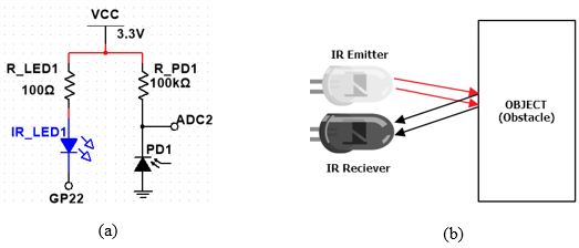
A basic IR proximity sensor schematic is given in figure 5. When GP22 is high, no voltage is seen across the IR LED. When GP22 goes low, a forward voltage is applied to the IR LED, which produces infrared light. When an object approaches the proximity sensor, the infrared light bounces off it and hits the IR photodiode, which produces a current and voltage. The current and voltage are therefore proportional to the proximity of the object. When the ADC reads the voltage, it reads the proximity of the object.

Figure 5 - (a) IR Proximity Sensor Circuit. (b) Detection of an object [2].
IR Circuit Design
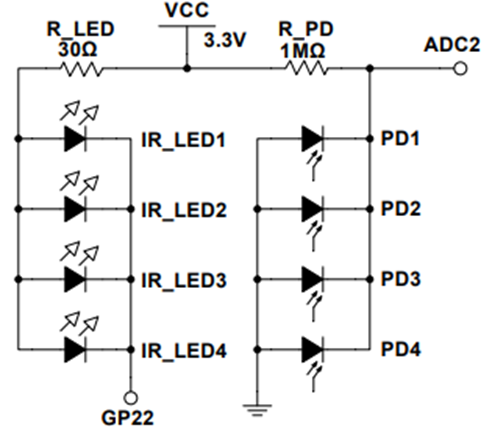
Since four proximity sensors are needed and only one ADC is available to read them, the following circuit was designed to turn on all IR LEDs at once and read all IR photodiodes at once. Since the IR photodiodes are in parallel, their voltages sum at the ADC. Once the ADC voltage falls below a specified threshold, all windows can be said to be down.

Figure 6 – IR Proximity Sensor Circuit Schematic
Programming the Proximity Sensor
First, the I2C bus must be initialized for the GPIO expander. Next, the ADC and GPIO are initialized for the proximity sensor. Then, a GPIO pin on the expander is initialized for an indicator LED.

The following function reads the distance of an object from the sensor. It reads the ADC when the IR LEDs are off to get the ambient IR. Next, it reads the ADC when the IR LEDs are on to get the reflected IR value. The difference between them is calculated, and then an average is taken to get the final distance value.

The function below takes the measured distance and determines whether the window is up or down based on a specified threshold. This threshold was set to 2000 for testing but will have to be calibrated once the sensors are installed on the windows. If the windows are down, then a green indicator LED will be turned on.

The main loop runs the distance function and the window function and then prints out the distance and window status on the console.

Testing the Proximity Sensor
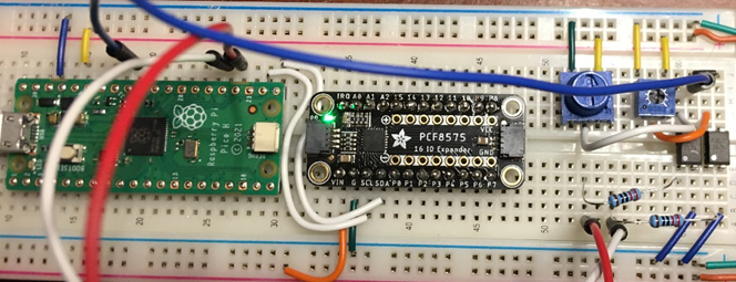
To test the proximity sensor circuit, it was first built on a breadboard and connected with the Pico. The code was run, and the distance was gathered with and without an object covering the sensor. When an object approaches the sensor, the distance increases. It may be better in a future revision of the code to name this variable “proximity” since the name distance is misleading.

Figure 7 - Testing the IR circuit
Table 3 – IR distance measurements with and without an object present

Summary
This week, Ian tested the revised temperature sensor circuit. Ian also revised the fan control and MCU pinout diagrams, as well as the battery mode program to reflect the change in the number of fans and relays. Next, Ian designed, programmed, and tested the IR proximity sensor circuit for determining window position.
References
[1] “IR Photodiodes | Engineering 360,” GlobalSpec. https://www.globalspec.com/ds/1031/areaspec/spec_enhanced_ir (accessed Jan. 17, 2023).
[2] Sharath, “IR Proximity Sensor with Arduino – FactoryForward,” Factory Forward. https://www.factoryforward.com/ir-proximity-sensor-arduino/ (accessed Jan. 17, 2023).

Comments