Week 26 : 2/13/2023 - 2/20/2023
- Group Progress

- Feb 20, 2023
- 4 min read
This week the group set out to test all functions of the project in a controlled environment.
Fan Control Testing and Troubleshooting
The fan control system involves the MCU, the GPIO Expander, the transistor switching array, the fans themselves, and a heap of connections. Thorough testing and troubleshooting were required to get this system to function correctly.
Fan Control Initial Test
After connecting all fans to the control module, the group first activated the entire transistor array to verify that power was being provided to the fans through the array. An entire fan array was non-functioning, along with a few random fans. Next, the group verified that each fan array was being triggered by its corresponding section on the transistor array. To do this, each transistor's base was activated one at a time from the fan control program. This made it immediately obvious that two of the arrays had been swapped while plugging them in.
Once the fan array cables were swapped to the correct positions, the group went through a checklist of all the transistors and made notes on each of the non-functioning ones. In doing this, the group discovered that none of the transistors connected to the PCF8575 were being triggered. Using an oscilloscope, the group discovered that the voltage at PCF8575 GPIO pins was very low.
Troubleshooting the PCF8575 GPIO Expander
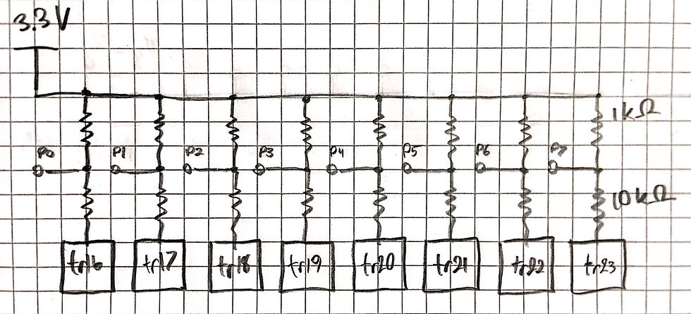
Doing a little bit of forum research, the general consensus seemed to be that pull-up resistors are required to drive transistors from the GPIO on the PCF8575. The group tested this on one of the pins by connecting a 1 kOhm pull-up resistor in the following configuration:

The above circuit worked, allowing the PCF8575 to trigger the base of the transistor, allowing current to flow through the fan. Since eight of the transistors receive their base from the PCF8575, the group had to add a pull-up resistor for each of the eight pins. The group calculated that the current limiting resistors at the bases of these transistors would need to be swapped to 10 kOhms. This gives a parallel resistance of 1.375 kOhms to the 3.3V supply.

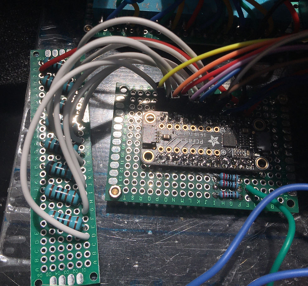
Since there was not enough space on the PCF8575 PCB, a new PCB had to be added to the control box to hold and connect all the resistors.

Once all changes were made, the group tested fan control from the PCF8575 and verified that the transistors and fans were being triggered and getting power appropriately. This brought the non-functioning array and a few other fans back to life
Troubleshooting Transistor Issues
Triggering the entire transistor array once more, only a few fans remained non-functioning. The group took an oscilloscope to the corresponding transistors to troubleshoot.
Transistor tr1 saw no voltage at the collector. Visually inspecting all connections from the transistor to the terminal block, the group discovered that the jumper from the terminal block to its PCB was disconnected. Soldering a new connection solved the issue.
Transistor tr5 saw no voltage at the base. The group used the oscilloscope to determine that the GPIO signal from the Pico was not reaching the board. A visual inspection revealed that the pin was not soldered properly. The connection was soldered and the issue was resolved.
Once these issues were addressed, all fans ran when triggered and shut off completely when not. The group moved on to system control tests.
Full System Fan Control Tests
IR Window Sensor Control
Next, we tested that our IR sensors would not just detect an obstruction, but would actually ensure the load is cut off if any of the 4 car windows were up. Shown below is the testing done for these sensors.
Presently, there appears to be an issue related to the strength of the emitted signal of the IR LEDs. For a strong signal, we will need in excess of 20mA per IR LED. Daniel will research a solution in the coming week.
Switching Cooling Modes Based on Temperature Sensors
Lastly, we tested the cooling mode switching functionality. Last week we determined that the thermistor circuits were reading accurately, but now needed to confirm their ability to switch airflow direction based on the temperature differences detected at each window. Shown below is our test.
Re-testing the Battery Monitoring Circuit on the new Raspberry Pi Pico
The group tested and troubleshot issues related to our battery level monitoring code. In particular, the ADC of the Raspberry Pi Pico is quite 'bouncy' as readings would fluctuate quite a bit. Noted by Allen Jones, a bit of hysteresis was to be programmed into the code to help offset any issues made by sudden increases/decreases in the supply voltage. Seen below is a video of our test.
The ADC during initial testing showed a difference of ~200mV between the expected input voltage and the actual voltage displayed. It was also noticed that this difference increased slightly as the input voltage increased. A rough, temporary correction was made in the code after testing the input voltage going into the ADC pin and ensuring the input voltage was accurate on a DMM and O-Scope. It should also be noted that the hysteresis code needs a slight rework which will be done by Ian. The switching of the battery level modes does not currently provide an adequate amount of time between states before deciding to switch.
Summary
This was an exciting week for the group since all the main functions of the system were verified to operate. Some minor tweaks will need to be made to the IR proximity sensor and battery monitoring program to smooth the remaining kinks in system operation. This coming Monday (2/20/2023), the group will meet on East Campus to wire the system into the PWM Charge Controller and Solar Panel for a mock test which will retest the parameters of the cooling test shown above. The group will also begin the discussion of nozzle designs for the intake fans.

Comments