Week 26 : 2/13/2023 - 2/20/2023
- Ian Matheson

- Feb 20, 2023
- 3 min read
This week, Ian set out to fix the issues with the battery mode switching program. This includes a fix of the hysteresis program and a mathematical correction of the low ADC voltage seen in the tests outlined in this week's group report.
Hysteresis Programming
The flowchart below shows how the hysteresis operates in the battery mode program.

Outside of any battery function, the default previous input voltage and previous battery mode are set to zero.

After getting the input voltage from the ADC, an if statement checks for at least a 50 mV difference between the input voltage and the previous voltage. If this condition is satisfied, the battery mode will be switched based on the previously defined thresholds. If not, then the battery mode is set equal to the previous battery mode.

If the current battery mode is not equivalent to the previous battery mode, then the previous input voltage is set to the current input voltage. If they are equivalent, then the previous input voltage stays the same. Before returning the battery mode, the program sets the previous battery mode equal to the current battery mode. The program is repeated each time the get_battery function is called in the program's main loop.

Testing the code, it works very well at keeping the battery mode stable after reaching new thresholds. In the printout below, observe that the Battery Mode remains at 1 even after the Vin falls below the lower threshold of 2.647 V

ADC Correction
As discovered in the testing earlier in the week, the voltage read by the ADC is not accurate to the actual input voltage. The group saw an approximately 200mV drop in the ADC reading compared to the DMM-measured voltage. Furthermore, the drop appeared to increase as the input voltage increased.
To gather data on this phenomenon, Ian first made an edit to the get_battery function so that it would take an average of 1000 readings. In the code below, the number of reps was set to 1000. The was made to print out Vadc.
Next, a power supply was set up to be read by the control module.

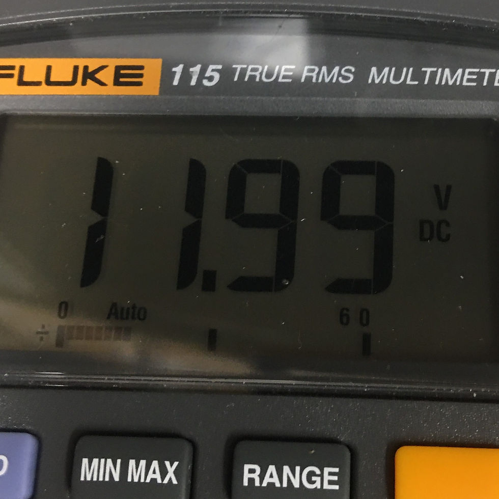
Starting with the PSU set to 12.00 V, DMM measurements of the PSU voltage and the ADC voltage were taken. The program was run to obtain the average ADC voltage reading. The PSU voltage was then increased by 0.30 V increments and the measurements were repeated through 15.00 V. The photos below show the actual supply voltage, the measured supply voltage, and the measured ADC voltage from left to right. Below these photos is the Vadc obtained in the program's printout.


The measurements were recorded in a google sheet for analysis. They are also shown in the table below.

The chart below compares the measured Vin to the ADC voltage. It shows how the difference between Vin and Vadc increases slightly as the supply voltage increases.

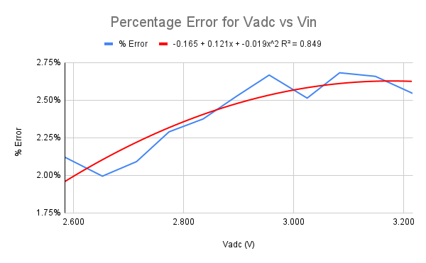
The % Error was calculated using the following equation and then plotted against the ADC voltage. This is shown in blue. In red is a polynomial trendline generated by google sheets. The equation for this trendline is given in the legend along with its R^2. The R^2 value describes how well the trendline fits the data, with a perfect fit having a value of 1.00.


The equation for the trendline above was applied to a new column to calculate the Trendline Error % for each supply voltage level. Finally, the Vadc Adjusted column is the Vadc added to the product of Vadc and the trendline error.

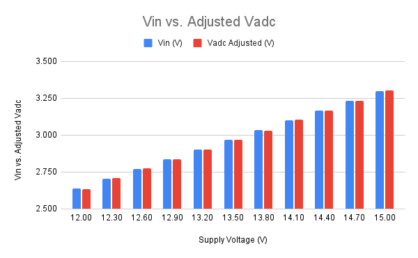
The chart below compares the measured Vin to the Adjusted ADC voltage. The adjusted ADC voltage fits the input voltage much better than the raw ADC voltage.

The same adjustment was applied to the get_voltage function in the code below. The accuracy of the ADC voltage should be drastically improved by this adjustment.

The thresholds in the battery_mode function were also edited to better reflect the Vin measurements from the DMM.

Summary
This week, Ian improved upon the previous iteration of the battery mode program by correcting the hysteresis code and creating an adjustment function for the ADC voltage. This will help the project by preventing the battery modes from changing rapidly at thresholds. The battery voltage readings will also be more accurate.


Comments