Week 7: 10/3/22 - 10/10/22
- Ian Matheson

- Oct 11, 2022
- 2 min read
Since the test results did not lean in the Peltier device's favor, the cooling method was scrapped in favor of ventilation. Earlier in the week, Daniel had drafted up a block diagram for the revised A.S.H.E. concept based on ventilation. Ian formatted the block diagram into modules for enhanced readability and structure. This is shown below.

With the deadline for the IEEE application for funding approaching, a Proposed Budget sheet was created to satisfy one of the requirements. Ian and Daniel worked together to decide on the components which best suited our needs. Ian's contributions to this sheet include batteries, humidity sensor, and both MPPT and PWM solar charge controllers appropriate for the solar panel and batteries.
Some basic calculations were performed in Octave to obtain the specifications for the batteries. Since each fan requires 2.2W of power, the required power for the 32 fans would be about 70.4 W
Preq = 32*2.2
Preq = 70.40 W
Based on the findings from last week's solar panel experiment, it was estimated that the 100W solar panel in the windshield could reliably provide about 40W of power. Therefore, the power needed from the batteries is the required power minus the solar power.
Pbat = Preq - SolarP
Pbat = 30.4 W
Since the design uses a battery in each window, the power required of each battery would be the total battery power divided by 4.
Psingle = Pbat/4
Psingle = 7.6 W
Deciding that the device should be able to run for up to 5 hours, we would need a battery which could provide 7.6 W for that period of time.
Pday = Psingle*5h
Pday = 38.0 Wh
We also needed a small battery, so looking into phone batteries with the required power yielded the following battery. This lithium polymer battery is rated for 3.7V and 10,000 mAh.
P = 3.7V*10mAh = 37Wh
With one of these in each window, the device should run for a bit less than 5 hours.

Since the fans require 12V, a DC/DC converter will be used to step up the voltage. With the battery specs known, it was time to find a solar charge controller. The following PWM controller was found. PWM was chosen for its cheap cost relative to MPPT, and because the system is not very power heavy.

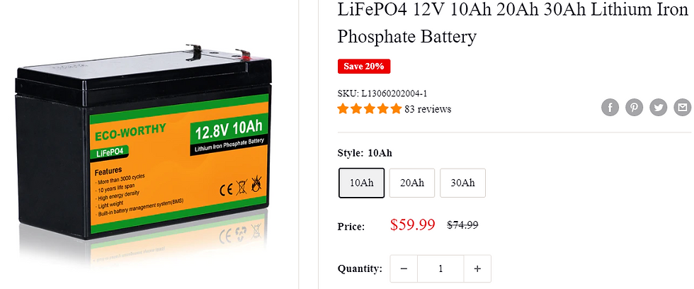
Alternatively, the solar panel, PWM charge controller, and four batteries could be swapped for a single large battery. This option would be a lot cheaper, however charging and storing the battery could be a challenge. Since the system requires 70 W at 12V,
Pday = 70*5
Pday = 350 Wh
Iday = 350 Wh/12V
Iday = 30 Ah

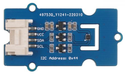
The following humidity sensor was found. This is the SHT-40 digital humidity sensor. Its operating range is from 0% to 100% humidity and -40°C to +125°C. It also measures temperature, which will allow us to measure the outside ambient temperatures.

Once the proposed budget sheet was complete, Ian completed the final draft of the application for funding, which Danial had started earlier in the week.

Comments