Weeks 16-21 : 12/5/22 - 1/9/23
- Ian Matheson

- Jan 17, 2023
- 5 min read
The objective for the break was to design and program the sensors for the control module using the Raspberry Pi Pico. This progress log lays out the details of this process.
Planning the MCU Pinout
Before any programming, the pinout was carefully planned. Since the project will utilize nearly all the pins on the Pico and GPIO expander, planning will be crucial to keep things neat and organized. A Google Sheet was used to lay out all the pins and their connections. This is shown in figure 1 below.

Figure 1 – Control Module MCU Pinout
Getting Started with The Raspberry Pi Pico and GPIO Expander
The Adafruit PCF8575 is designed to be used with CircuitPython, which is a version of Python with added hardware support. The Raspberry Pi Pico is fully compatible with CircuitPython, and Adafruit has extensive documentation on this very subject [1]. After following the steps, the Pico was set up to be programmed with CircuitPython in the Thonny IDE.
To use the PCF8575, headers were first soldered onto the board. The SCL and SDA pins were wired to GP14 and GP15 respectively. Note that this was modified to GP16 and GP17 on the MCU pinout after testing. Ground and VIN were connected from the Pico.
Next, the PCF8575 library was downloaded from the Adafruit website and installed on the Pico’s freshly created CIRCUITPY drive. Test code was copied from the Adafruit website and modified to work with the Pico. The code is given below. In figure 2, an LED connected to the PCF8575 is lit whenever the button is pushed.
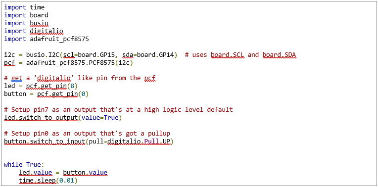
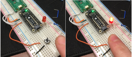
Figure 2 – Lighting up an LED with a pushbutton through the PCF8575.
Relay Control Test Program
This project uses optocoupled relays to switch the 12V fans on and off. To test the control of a relay with the Pico, a circuit was built up on breadboard which would power an LED from an external power supply whenever the Pico supplied 3.3V to the connected GPIO pin. The code cycles the pin on and off every 4 seconds.

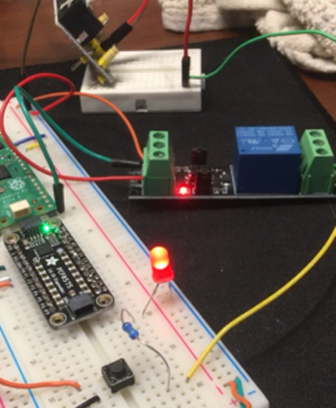
Figure 3 – Relay test circuit.
Battery Voltage Monitor Programming
Daniel created the voltage divider from the battery to the MCU. The divider creates a voltage that ranges from 2.618 V when the battery is at 12 V and 2.75 V when the battery is at 12.6 V. When the battery is at its maximum voltage of 15V, the divider voltage is 3.26 V, which falls right under the 3.3 V maximum of the Pico.
The job of the battery voltage monitor program is to switch the number of fans based on the battery voltage. Six thresholds were defined based on the voltage of the battery, but since the MCU reads these voltages at the lower levels provided by the divider, the thresholds must be defined in terms of these lower voltages. The following table defines these thresholds. The divider voltages were obtained using the following operation to obtain the distance between five evenly spaced values.
Table 1 – Battery Voltages and corresponding Divider Voltages for 5 battery modes.

The following function takes the input voltage (0-3.3 V) and determines the battery mode using the thresholds defined in table 1.

The Pico has a 12-bit ADC. However, this is scaled up to 16 bits to comply with CircuitPython’s API [2]. Therefore, the following equation can be used to convert the raw ADC value to a voltage.

This equation is used in the function get_voltage(raw). Its definition and usage in the main loop are given below.

Temperature Sensor Design & Programming
Thermistors will be used for four temperature sensors in the Solar Powered Ventilation System for Parked Cars. A thermistor is a semiconductor that acts like a resistor whose resistance is dependent on the temperature [3]. The resistance of the thermistor can be used to calculate the temperature.
Thermistor Circuit Design & Calculations Temperature Calculations
The thermistors used for the sensors are NTC3950 thermistors. The values in table 2 were obtained from their datasheet [4].
Table 2 – Given values from the NTC3950 datasheet.

To determine resistance, the thermistor is first placed in a voltage divider circuit as shown in figure 1. Rk is selected to match R0 so that the ADC voltage will be halved at 25 °C. The voltage seen by the MCU’s ADC is then used to calculate the resistance of the thermistor RTh using the voltage divider equation in (1).
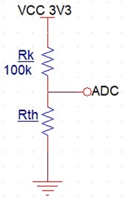
Figure 4 – Thermistor Voltage Divider Circuit.

Since the β parameter has been given, the β parameter equation can be used to solve for the temperature, T [5].

The resulting T value is in Kelvin, so 273.15 is subtracted from it to get the temperature in Celsius. This is then converted into Fahrenheit in (6).

Programming the Pico to Read Temperature
To get the voltage seen by the ADC, the raw value of the ADC must first be read. The raw value is then converted to a voltage using (1). The following code gets the voltage from a thermistor voltage divider.

To convert the voltage Vin to a temperature, the following code is used.

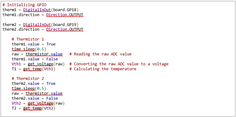
To read the voltages of multiple thermistor circuits on one ADC pin, a GPIO pin was connected in place of VCC for each circuit. The following code was then used to power each circuit, read its voltage, and then power it off before doing the same for the next circuit.
Parallel Thermistor Circuits into One ADC
With only three ADC ports on the Raspberry Pi Pico, our design requires that all four thermistor circuits can be read by the same ADC. To do this, the outputs of each thermistor circuit must be isolated from each other. Starting with just two transistor divider circuits, the first attempt was a summing amplifier circuit, as shown in figure 5 below. To test this design, potentiometers were used in place of the thermistor divider circuit.
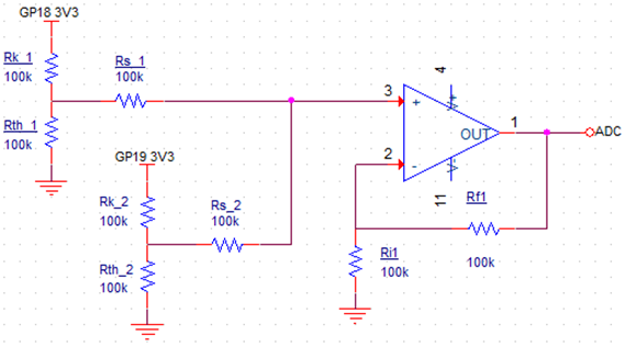
Figure 5 – Summing circuit for two transistor dividers.

Figure 6 – Figure 2 circuit on breadboard.
The above design failed in isolating the outputs of each thermistor circuit. The voltage output of each thermistor divider was dependent on the other. The screenshots below showcase this behavior. In (a), the first potentiometer was set to its midpoint so that the voltage was divided in half. The second potentiometer was set to its lower extremity. In (b), the first potentiometer was left in the same position, and the second potentiometer was increased to match V1 from (a).

Figure 7 – (a) Pot1 set to midpoint and Pot2 to lower extreme. (b) Pot1 in the same position, Pot2 set to match V1 from (a).
To resolve this issue, the group met up on 1/8/2023 to discuss solutions. Daniel had the idea to use optocouplers to isolate the outputs. This design later proved to be viable and will be discussed in detail in the group log and in Ian’s log for Week 21.
Summary
Over the course of the break, Ian planned the pinout for the MCU and peripherals, got the Raspberry Pi Pico running on CircuitPython, and integrated and tested the PCF8575 GPIO expander. Next, Ian wrote and tested a relay control program and a program for determining battery mode based on the battery voltage. Finally, Ian designed a temperature sensor circuit using a thermistor, wrote a program to read the temperature from it, and devised a faulty method for isolating circuit outputs from the ADC.
References
[1] K. Rembor, “Installing CircuitPython | Getting Started with Raspberry Pi Pico and CircuitPython | Adafruit Learning System,” Adafruit. https://learn.adafruit.com/getting-started-with-raspberry-pi-pico-circuitpython/circuitpython (accessed Jan. 16, 2023).
[2] C. Nelson, “ADC | CircuitPython Libraries on any Computer with Raspberry Pi Pico | Adafruit Learning System,” Adafruit. https://learn.adafruit.com/circuitpython-libraries-on-any-computer-with-raspberry-pi-pico/adc (accessed Jan. 16, 2023).
[3] “What Is A Thermistor And How Does It Work?,” Omega Engineering, Inc. https://www.omega.com/en-us/resources/thermistor (accessed Jan. 15, 2023).
[4] “Specifications for NTC Thermistor.”
[5] “Thermistor,” Wikipedia. https://en.wikipedia.org/wiki/Thermistor#B_or_%CE%B2_parameter_equation (accessed Jan. 15, 2023).

Comments